
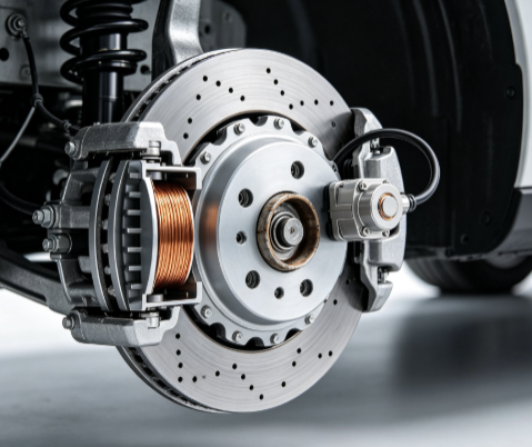
1. Introduction: The Sensor That Decides Whether Your ABS Works at All
I have been diagnosing and specifying ABS components for over a decade, and I can tell you that the most frustrating repair in the shop is not the one that requires the most skill. It is the one where the sensor gets replaced, the light goes out, and then twenty kilometres later it comes back on.
That loop — code points to a location, part gets swapped, fault returns — happens because the code tells you where the problem is, not what the problem is. A wheel speed sensor fault code can be triggered by at least five separate physical faults, and only one of them is the sensor itself. The others are wiring, connectors, the tone ring, the wheel bearing, or the air gap between the sensor and the ring.
About 70–80% of ABS light complaints trace back to a sensor or its wiring. That means the sensor circuit is the right place to start — but starting there and stopping there are two different things. The diagnostic sequence matters as much as the diagnostic tool.
A wheel speed sensor feeds data to the ABS module, the traction control system, and the vehicle ECU. When the signal is lost or corrupted, the module sets a fault code and disables the system rather than operate on bad data. The foundation brakes still work, but anti-lock function, traction control, and stability control may all be reduced or disabled.
This guide walks through the symptoms, the diagnostic sequence, and the testing parameters that separate a confirmed sensor failure from a wiring fault, a tone ring problem, or a bearing issue that masquerades as a sensor code.
2. How a Wheel Speed Sensor Fails
Wheel speed sensors are relatively durable components. In ideal conditions, they can last the life of the vehicle. But the wheel hub is not an ideal environment. The sensor is bolted to a non-spinning portion of the hub assembly, exposed to road salt, mud, snow, brake dust, and temperature cycling from -40°C to over 100°C.
There are two sensor architectures, and they fail differently.
Passive (inductive) sensors use a wire coil and permanent magnet. As the tone ring teeth pass the sensor tip, the changing magnetic field induces an AC voltage. The signal amplitude and frequency rise with wheel speed. Passive sensors have a typical coil resistance of 1,000–2,500 Ω. They are simple and robust, but they produce weak signals at very low speeds and are gradually being replaced by active sensors.
Active (Hall-effect or magnetoresistive) sensors require an external power supply from the ABS module. They produce a digital square-wave signal that is clean and consistent even at very low wheel speeds. Active sensors typically have very high internal resistance (megaohm range) or no measurable coil resistance at all — the measurement method is completely different from passive sensors.
Common failure causes include internal coil or circuit failure (open or short), corroded connectors, chafed or broken wiring in the harness, debris accumulation on the magnetic sensor tip, tone ring damage or rust jacking, excessive wheel bearing play that disrupts the air gap, and water intrusion at the connector seal.
The practical lifespan of a wheel speed sensor is typically 60,000 to 150,000 miles. Frayed wiring or damaged connectors can cause earlier failure, and driving with worn wheel bearings accelerates sensor damage by allowing hub movement that disrupts the signal.
3. The Eight Symptoms You Should Never Ignore
The symptoms of a failing wheel speed sensor range from obvious to subtle. Some appear immediately; others only under specific driving conditions. Here are the eight most common, ordered from most to least frequent.
1. ABS warning light illuminated. This is the most prevalent symptom and often the first indication that something is wrong. When the ABS module detects a missing or implausible signal from a wheel speed sensor, it stores a fault code and turns on the ABS warning light. At that point, the anti-lock function is disabled.
2. Traction control and stability control disabled. Because the ABS module shares wheel speed data with the traction control (TCS) and electronic stability control (ESC) systems, a sensor fault often triggers multiple warning lights. On some vehicles, a "Service StabiliTrak" or "Service ESC" message appears alongside the ABS light.
3. Longer stopping distance on slippery surfaces. Without ABS, the wheels can lock under hard braking on wet, icy, or gravel surfaces. The vehicle may slide instead of steering, and stopping distance increases. This is the most safety-critical symptom.
4. Brake pedal pulsation at the wrong time. A failing sensor can send an erratic signal that the ABS module interprets as a wheel about to lock. The module activates the ABS pump when it should not, producing a pulsating or grinding feeling through the brake pedal during normal braking or at low speeds.
5. Erratic or fluctuating speedometer. The speedometer reading is derived from wheel speed sensor data. A failing sensor can cause the speedometer to display incorrect readings, drop to zero intermittently, freeze, or jump erratically.
6. Unexpected ABS activation at low speeds. A noisy or intermittent sensor signal can trigger ABS activation during low-speed braking or parking manoeuvres when the system should not be active. This may feel like the brakes are grabbing or pulsing when they should be smooth.
7. Vehicle pulls to one side during braking. If the ABS module receives a valid signal from three wheels and an invalid signal from the fourth, it may apply uneven brake pressure, causing the vehicle to pull toward the side with the faulty sensor.
8. Cruise control or hill-hold features malfunctioning. On many vehicles, the cruise control system uses wheel speed data. A sensor fault can cause the cruise control to disengage unexpectedly or fail to engage at all.
Any one of these symptoms warrants immediate diagnosis. The foundation brakes will still stop the vehicle, but without ABS, the risk of wheel lock-up and loss of steering control under hard braking is significantly increased.
4. Diagnostic Step 1: Scan Tool and Live Data
The first step in any wheel speed sensor diagnosis is retrieving the fault codes with an ABS-capable scan tool. A basic OBD-II scanner may not read ABS codes — you need a tool that supports the chassis (C) code range.
The common generic codes are:
C0035 — Left front wheel speed sensor circuit
C0040 — Right front wheel speed sensor circuit
C0045 — Left rear wheel speed sensor circuit
C0050 — Right rear wheel speed sensor circuit
These codes vary slightly by manufacturer, but the pattern is consistent across most domestic and import vehicles. Some platforms also document sub-codes that indicate the specific fault type: C0040-02 (short to ground), C0040-05 (short to power/open), C0040-0F (erratic), and C0040-18 (low amplitude).
The scan tool gives you the fault code. The live data gives you the diagnosis. Drive the vehicle at a steady low speed — 5 to 10 mph — and compare the wheel speed readings from all four sensors on the scan tool display. A healthy sensor produces a smooth, consistent reading that tracks the other wheels. A faulty sensor flat-lines, drops out intermittently, or produces a noisy, erratic reading.
If one wheel is jumping erratically — for example, reading 5 mph, then 0, then 12 — while the others are steady, you have found the problematic corner. This live-data comparison is the most reliable first-pass diagnostic because it tests the entire signal path under real operating conditions.
A useful confirmation technique: wiggle the sensor connector while watching the live data. If the reading changes, the fault is in the connector or the wiring near the connector, not in the sensor itself. On some vehicles, turning the steering wheel to full lock while monitoring live data will reveal a chafed wire in the front sensor harness.
Important limitation. Live data shows you which sensor is reporting bad data. It does not tell you whether the sensor, the wiring, the connector, or the tone ring is the root cause. That requires electrical testing and visual inspection.
5. Diagnostic Step 2: Visual Inspection and Harness Checks
Before any electrical testing, perform a thorough visual inspection. This step costs nothing and frequently identifies the fault without further testing.
Connector inspection. Disconnect the sensor connector and examine both halves for corrosion, water intrusion, bent pins, or a broken locking tab. Corrosion appears as green or blue deposits on the terminals. A cracked connector housing or a missing seal allows water to enter the circuit, causing intermittent faults that appear and disappear with weather changes.
Harness routing and condition. Trace the sensor wiring from the connector back toward the chassis. Look for chafed insulation where the harness passes near the strut, the fender liner, or any rotating component. The short pigtail between the sensor body and the first connector is a known common failure point on many GM and Ford applications.
Sensor body and tip. Remove the sensor and inspect the tip. Metal debris or brake dust accumulated on the magnetic tip can corrupt the signal. Clean the tip and reinstall before condemning the sensor. Also check for cracks in the sensor body or damage to the mounting bracket.
Tone ring condition. The tone ring (or magnetic encoder ring) is the toothed or magnetized ring that the sensor reads. Inspect it for missing teeth, cracks, rust jacking, or debris. Rust jacking occurs when corrosion between the tone ring and the hub expands, lifting the ring and changing the air gap. On many modern vehicles, the tone ring is integrated into the wheel bearing hub assembly — if the ring is damaged, the entire hub must be replaced.
Wheel bearing play. Grab the tire at the top and bottom and rock it. If you feel movement or hear a clunk, the wheel bearing has excessive play. A worn bearing allows the hub to move, which changes the air gap between the sensor and the tone ring and disrupts the signal. A new sensor will not fix a bearing problem.
Air gap measurement. The air gap between the sensor tip and the tone ring must be within specification. The typical front wheel air gap is 1.10–1.97 mm, and the rear wheel air gap is 0.42–0.80 mm. An excessive air gap weakens the signal; a zero gap risks contact and sensor damage.
6. Diagnostic Step 3: Electrical Testing by Sensor Type
If the visual inspection does not reveal the fault, proceed to electrical testing. The test method depends entirely on whether the sensor is passive or active. Applying the wrong method to the wrong sensor type can condemn a good sensor or pass a faulty one.
Passive (inductive) sensor testing. Measure the resistance across the sensor terminals with a digital multimeter. The typical specification is 1,000–2,500 Ω. Some sources narrow the range to 1,275–1,495 Ω for front sensors and 1,260–1,540 Ω for rear sensors on specific platforms. A reading of infinite resistance indicates an open circuit. A reading near zero indicates a shorted coil. A reading outside the range but not infinite may indicate a partially failed sensor that works intermittently.
Next, perform the dynamic AC voltage test. Set the multimeter to AC volts (mV range if available). Leave the probes connected to the sensor terminals and spin the wheel by hand. A good passive sensor generates a small AC voltage — typically 0.5 to 1.0 V AC at moderate hand-spin speed. The voltage should rise smoothly as wheel speed increases. A sensor that produces no voltage, or produces an erratic signal, is faulty.
Active (Hall-effect / magnetoresistive) sensor testing. Active sensors require power from the ABS module. Do not attempt to measure coil resistance on an active sensor — there is no coil to measure. Instead, verify the supply voltage at the connector with the ignition on. The supply should be approximately battery voltage (12 V) on the power pin, with a good ground on the ground pin.
To test the signal output, you need either a lab scope or a scan tool that displays live wheel speed data. Spin the wheel and observe the signal. A good active sensor produces a clean square wave that changes frequency with wheel speed. The signal should be present even at very low speeds — this is the primary advantage of active sensors over passive types.
Circuit continuity testing from the ABS module. If the sensor tests good at the wheel but the fault code persists, test the wiring from the ABS module connector to the sensor connector. Disconnect both ends and measure resistance between the corresponding pins. The resistance should be near zero (typically under 2 Ω). A high reading indicates a corroded or damaged wire. Also check for continuity to ground — any continuity between a sensor wire and ground indicates a short.
This step-by-step circuit testing is what separates a confirmed diagnosis from a parts-swapping guess. A technician who probes the sensor from the ABS module connector, verifies the wiring continuity, and then tests the sensor itself will find the fault that a simple code reader misses.
7. Head-to-Head: Passive vs. Active Sensor Diagnostic Comparison
Diagnostic Parameter | Passive (Inductive) | Active (Hall / MR) |
External power required | No | Yes (from ABS module) |
Signal type | Analog AC voltage | Digital square wave |
Resistance measurement | 1,000–2,500 Ω typical | No coil — do not measure resistance |
Dynamic test method | AC voltage with wheel spin | Supply voltage + scope/scan tool |
Expected AC voltage (hand spin) | 0.5–1.0 V AC | Not applicable |
Low-speed signal quality | Weak / unreliable at very low speeds | Clean signal even at very low speeds |
Wires | 2 wires | 2 or 3 wires (power, ground, signal) |
Common failure mode | Open coil, shorted coil, chafed wiring | Supply/ground fault, internal circuit failure |
Primary diagnostic tool | Multimeter (ohms + AC volts) | Scan tool (live data) or lab scope |
Typical vehicle usage | Older vehicles, some heavy commercial | Most modern ABS/ESC systems |
8. The Tone Ring and Air Gap: What Most Diagnostics Miss
The sensor is only half of the measurement system. The tone ring is the other half, and it is the component most frequently overlooked when a sensor code appears.
The tone ring (also called an exciter ring or encoder ring) is mounted on the rotating hub or axle and passes close to the sensor tip. As the ring rotates, the teeth or magnetic segments change the magnetic field at the sensor, generating the signal. If the ring is damaged, rusted, or contaminated, the signal is corrupted regardless of how good the sensor is.
Inspection points. Look for missing or damaged teeth on a toothed ring. On a magnetic encoder ring (common on modern vehicles), look for cracks, discoloration, or areas where the magnetic pattern has been disrupted. Rust jacking — where corrosion between the ring and its mounting surface lifts the ring — changes the air gap and weakens the signal.
Air gap verification. After installing a replacement sensor, verify the air gap between the sensor tip and the tone ring. The typical specification for front wheels is 1.10–1.97 mm, and for rear wheels 0.42–0.80 mm. A feeler gauge can be used where access permits. Excessive air gap is a common cause of weak signal codes that reappear after sensor replacement.
Wheel bearing integration. On many modern vehicles, the tone ring is integrated into a sealed wheel bearing hub assembly. If the bearing is worn or the ring is damaged, the entire hub assembly must be replaced. This significantly changes the repair cost compared to a stand-alone sensor replacement — parts alone may run $100–$350, and labour time increases.
9. Case Study: The VW Sagitar Sensor That Kept Coming Back
The most instructive real-world case study for wheel speed sensor misdiagnosis comes from a recurring complaint on the 2017–2018 Volkswagen Sagitar.
The complaint. The owner reported that ABS and ESP warning lights illuminated intermittently, particularly after car washes or driving through water. The vehicle was under normal maintenance, no accident history, no modifications. The sensor had already been replaced multiple times, and the fault kept returning after a few days or weeks.
The pattern. The fault appeared after water exposure and cleared itself after the vehicle dried out. This intermittent, moisture-related pattern is the signature of a connector or harness fault, not a sensor failure. A failed sensor produces a permanent fault; a moisture-sensitive fault points to the connector seal, the wiring insulation, or water intrusion in the circuit.
The diagnostic approach. The technician monitored live wheel speed data while wiggling the sensor connector and spraying water on the connector area. The right-front wheel speed reading dropped out momentarily when the connector was disturbed. Further inspection revealed a partially degraded connector seal that allowed water to enter the terminal cavity. The sensor itself tested within specification.
The lesson. The repeated sensor replacements were not solving the problem because the sensor was not the problem. The connector seal was allowing water intrusion, and the moisture was disrupting the electrical contact intermittently. The correct repair was a connector replacement, not another sensor. This case illustrates why the diagnostic sequence — scan tool, live data, visual inspection, electrical testing — must be followed in order. Skipping the visual inspection and going straight to sensor replacement is the most common cause of repeat repairs.
The Sagitar case is not unique to Volkswagen. It reflects a broader pattern where ABS sensor codes are treated as sensor replacement directives rather than diagnostic starting points. The fault code identifies the circuit; the technician must identify the component within that circuit.
10. Replacement Cost and Prevention
Cost expectations. A stand-alone wheel speed sensor replacement typically costs $150–$400 at a shop, including parts and labour. DIY parts alone run $30–$100 per sensor. If the sensor is integrated into the wheel bearing hub assembly, parts alone can reach $100–$350, and the total repair cost rises to $200–$600+. Dealer repairs for integrated hub assemblies can exceed $650.
Prevention practices. There is no way to eliminate wheel speed sensor exposure to the environment, but several practices extend sensor life. Apply dielectric grease to the connector terminals during brake service or tire rotation — this is particularly important in salt-belt regions where road salt accelerates corrosion. Secure the sensor harness away from struts and rotating parts to prevent chafing. Inspect the sensor and connector during every tire rotation and brake service. When replacing a sensor, clean the mounting hole thoroughly — rust and corrosion frequently seize the old sensor, and the new sensor will not seat properly if the hole is not cleaned.
OEM vs. aftermarket. The choice between OEM and aftermarket sensors affects long-term reliability. OEM sensors are designed and tested for the specific vehicle platform, with connector geometry and electrical characteristics matched to the ABS module. Aftermarket sensors vary widely in quality. The cost difference is typically $20–$50 per sensor, but the reliability difference can be significant — particularly on platforms where the sensor is integrated into a sealed bearing assembly and replacement labour is high.
11. Frequently Asked Questions
Q: Can I drive with a faulty ABS wheel speed sensor?
Short distances at low speed are generally acceptable, but the ABS and traction control systems may be disabled. The foundation brakes still work — the vehicle will stop — but without ABS, the wheels can lock under hard braking on wet or slippery surfaces, increasing stopping distance and reducing steering control. Plan repairs promptly.
Q: How do I know which wheel speed sensor is faulty?
An ABS-capable scan tool will read the fault code and identify which circuit is affected. The generic codes are C0035 (left front), C0040 (right front), C0045 (left rear), and C0050 (right rear). Confirm the fault by comparing live wheel speed data across all four wheels — the faulty wheel will show a flat, erratic, or dropped signal.
Q: What resistance should a wheel speed sensor have?
For a passive (inductive) sensor, the resistance should be between 1,000 and 2,500 Ω. Some platforms specify a narrower range, such as 1,275–1,495 Ω for front sensors. Active (Hall-effect) sensors do not have a measurable coil resistance — attempting to measure resistance on an active sensor with a standard ohmmeter will produce a misleading result.
Q: How do I test a wheel speed sensor with a multimeter?
For a passive sensor: measure resistance across the terminals (expect 1,000–2,500 Ω), then set the meter to AC volts and spin the wheel by hand. A good sensor generates 0.5–1.0 V AC. For an active sensor: verify supply voltage at the connector with the ignition on, then use a scan tool to monitor live wheel speed data while spinning the wheel.
Q: What is the difference between a passive and an active ABS sensor?
A passive sensor uses a coil and magnet to generate an AC voltage that changes with wheel speed. It requires no external power but produces weak signals at very low speeds. An active sensor uses a Hall-effect or magnetoresistive element and requires power from the ABS module. It produces a clean digital signal even at very low speeds. The diagnostic methods for the two types are completely different.
Q: Can a bad wheel bearing cause a wheel speed sensor code?
Yes. A worn wheel bearing allows the hub to move, which changes the air gap between the sensor and the tone ring. The sensor may be perfectly functional, but the signal is disrupted because the ring is not passing the sensor at the correct distance. If the bearing has play, replacing the sensor alone will not fix the fault. On vehicles with the tone ring integrated into the hub bearing, the entire hub assembly must be replaced.
Q: Why does my ABS light come on only after it rains?
A moisture-sensitive ABS fault is almost always a connector or wiring issue, not a sensor failure. Water enters the connector through a degraded seal and disrupts the electrical contact intermittently. The sensor itself is sealed and does not develop moisture-sensitive faults under normal conditions. Inspect and replace the connector seal before replacing the sensor.
Q: How long do wheel speed sensors typically last?
In normal driving conditions, wheel speed sensors can last 60,000 to 150,000 miles or more. Exposure to road salt, mud, and temperature cycling reduces lifespan. Frayed wiring or damaged connectors can cause earlier failure, and driving with worn wheel bearings accelerates sensor damage.
12. Final Thoughts
Let me leave you with this.
A wheel speed sensor fault code is not a sensor replacement directive. It is a circuit fault code. The sensor is one component in a chain that includes the connector, the wiring harness, the tone ring, the wheel bearing, and the air gap between the sensor and the ring. Any one of those components can produce the same fault code, and replacing the sensor without testing the rest of the chain is the most common cause of repeat repairs.
The diagnostic sequence is straightforward: scan tool for codes and live data, visual inspection of the connector, harness, sensor tip, tone ring, and bearing, then electrical testing by sensor type. Passive sensors get a resistance measurement and an AC voltage test. Active sensors get a supply voltage check and a scope or scan tool signal verification. The resistance of a passive sensor should read 1,000–2,500 Ω, and the AC voltage should reach 0.5–1.0 V AC during hand spin.
The VW Sagitar case is the lesson: intermittent faults that appear after rain are almost always connector or wiring issues, not sensor failures. The moisture finds the weak point in the circuit, and the sensor gets blamed because the code points at its location.